Servo Motor Communication Protocol
An STM32 servo tester: read a potentiometer through an SPI ADC and drive a servo with a matching PWM signal.
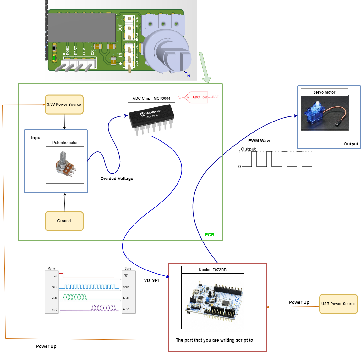
A WARG firmware project: a servo motor tester. A potentiometer sets the position; an external MCP3004 ADC digitizes it and sends it to an STM32 over SPI; the MCU turns that value into a 50 Hz PWM signal that drives the servo.
- Read a potentiometer through an external MCP3004 ADC over SPI on an STM32.
- Generated a 50 Hz PWM signal (1 to 2 ms pulse, 5 to 10% duty) with TIM1 to drive a servo.
- Mapped the ADC's 10-bit value to the timer's compare register for real-time control.
01The signal path
Potentiometer (0 to 3.3 V) → MCP3004 ADC → STM32 over SPI → PWM out to the servo. Turning the pot moves the servo in real time.
02SPI + ADC
Configured SPI1 as a full-duplex master (data size, bit order, and clock polarity/phase set from the MCP3004 datasheet) with a GPIO chip-select, reading the 10-bit ADC value each loop.
03PWM
Set up TIM1 for a 50 Hz signal (20 ms period) and mapped the ADC's 10-bit range to a 1 to 2 ms pulse by writing the timer's compare register.
Want to talk through how I built this?